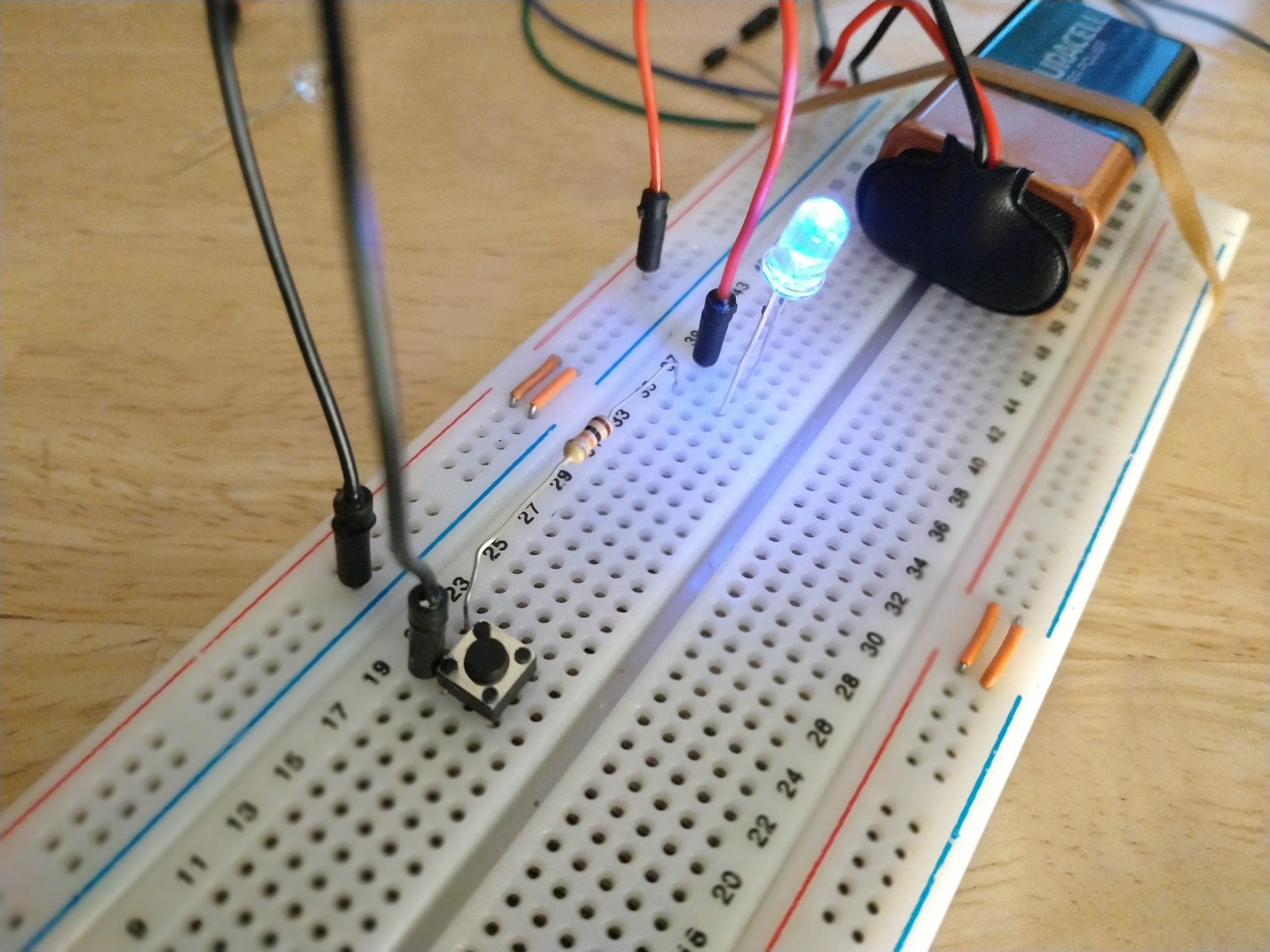
In this tutorial, we will learn how to use a prototyping plate to make a simple LED and push button assembly. To make this setup you will need:
- a prototyping board
- an LED
- a 9V battery with its clip
- a resistor of 10 KOhms
- a push button
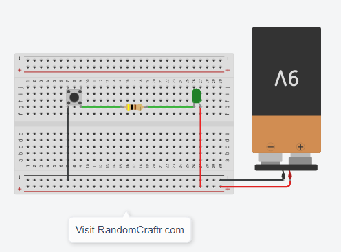
Mounting
The assembly is carried out using the diagram and the video below:
Functioning
To understand this assembly, we start from the red wire of the battery. The wire goes through the LED first. This component emits light under certain conditions. Then we come to resistance. This component has the role of protecting the LED. Indeed, the LED has a very small internal resistance and thus, causes the equivalent of a short circuit if directly connected to a battery. The resulting current could damage the LED or the battery (U=RxI, R small therefore I very large). To decrease the current, we introduce a resistor in the circuit (U=RxI, we increase R, we therefore decrease I). Finally the push button closes the circuit and makes it possible to supply the LED and thus to light it.
In case of problems
Some common problems can appear on this assembly:
- The LED does not go out : turn the push button a quarter turn. The legs that are connected by the push button must not be on the same column of the breadboard.
- The LED does not light up : invert the direction of the LED. The LED is a component which has an on direction and a blocking direction, on the principle of the diode. The longer leg, called the anode, should be on the + side of the power supply. The shortest leg, on the side where the LED has a bevel, is called the cathode and is located on the side – of the power supply.
