
This content is made available by Adam Meyer, licensed under CC BY-SA 3.0.
OK, so say you have this crazy cool idea where you need to control a ton of LEDs (I know, I know… LEDs). You looked at the multiplexer article, and that was great, but this idea is so cool, you need individual control of each LED, and turning them on one at a time just won’t do. Well again, we are here to help, and now it’s time to introduce you to the Shift Register. Not just any shift register, the super cheap, incredibly awesome 74HC595 8-bit Shift Register!
What does a Shift Register do?
Basically a shift register will, in the end, let you expand on the digital outputs you have on your mictrocontroller. Each one of these 74HC595s can act like 8 more digital outputs, and you can daisy chain them. So you could hook 8 of them up next to each other and have control of 64 outputs.
But the way it works is a little confusing to think of at first, and these are helpful enough that it is really worth understanding what the heck is going on under the hood.
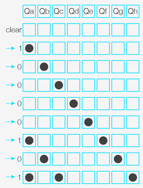
You can imagine a shift register as a row of chairs. In this particular case, with the 74HC595, we have a row of 8 chairs. Each chair is either empty (0), or someone is sitting it (1).
Now, every 10 seconds or so, someone rings a bell, and everyone has to get up and move one chair to the right. If there was someone in that rightmost chair, well they just go away. In that leftmost chair, you can either tell someone to sit in it, or just leave it empty.
Now bringing this idea back to the 74HC595: This shift register consists of 8 output pins, which are either high (1) or low (0). When you pull the SRCLK (Serial Clock) pin high (analogy to ringing the bell), every pin moves one to the right. The Last pin drops out, and the new pin’s state is defined by the SER (Serial) pin, and you can set that to either 1 (HIGH) or 0 (LOW).
How does this let me control LEDs again? Well, say you have 8 LEDs hooked up to the shift registers outputs, and we want to turn on the 1st, 3rd and the 8th LED. So… what we can do is clear out the register so all LEDs are off. Then we put in one high, move it right 4 spots, add one high, move it over 1, then add another high. See the image on the right, it will make more sense.
The great thing is that the shift register has this pin called RCLK or register clock. You can hold this pin LOW while you get everything setup and nothing on the display pins will change. Then when you are done, and everything is how you want, you pull the RCLK HIGH and the 74HC595 will display the new settings. So even though we are changing values in the register in 8 steps, it looks like it was just one step.
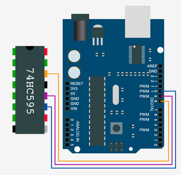
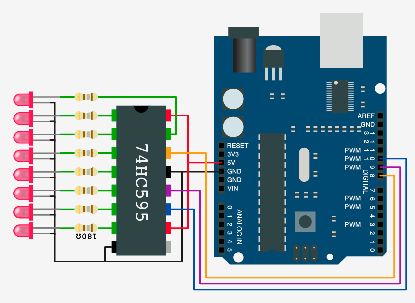
Hooking it up
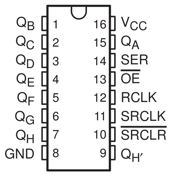
We are going to start simple. There are really just 3 connections you need aside from power to make this work. But as soon as power and the LEDs are all connected, it starts looking scary. But it’s not, so stick with us. – You can see a spec sheet for the 74HC595 here.
- Vcc
Up to 6V (needs to be the same voltage as your microcontroller) – Usually 3.3 / 5v - QA to QH
Shift Register Outputs. - SER:
(Serial) Input for the next pin that gets shifted in. - SRCLK
(Serial Clock) When this pin is pulled high, it will shift the register. - RCLK
(Register Clock) Needs to be pulled high to set the output to the new shift register values, This must be pulled high directly after SRCLK has gone LOW again. - SRCLR
(Serial Clear) Will empty the whole Shift Register if pulled LOW, must be pulled High to enable. - OE
(Output Enable) This pin enables the output when tied to GND, & disabled when HIGH.
How we make it work
Whenever the signal on the SERCLK-pin goes high, all the values get shifted to the right, and a new value gets shifted in (Whatever SER is set to). After you shifted in your new value, to see the changes made, you must also set the RCLK pin HIGH in order to update the output-pins with the new data. We wanted to get your’s up and running as quick as possible, so we put together some code for the Arduino, and AVR microcontrollers: see below for code examples.
The Arduino example enables individual control over the register pins. However the AVR example currently does not and must be fed a binary sequence. If you are interested in helping transcode the Arduino code into AVR (or any other language) so it will support individual pin control pleas let us know.
setRegisterPin(2, HIGH);
setRegisterPin(3, HIGH);
setRegisterPin(4, LOW);
setRegisterPin(5, HIGH);
setRegisterPin(7, HIGH);

//Once you have set the desired changes to the
//register pins, you will need to call writeRegisters
//before it is displayed. Only do this at the end,
//and not after each setRegisterPin call because this
//function takes some time to write the values.
//writeRegisters takes about 1ms per 10 of
//the shift registers you have chained (80 pins)
writeRegisters();
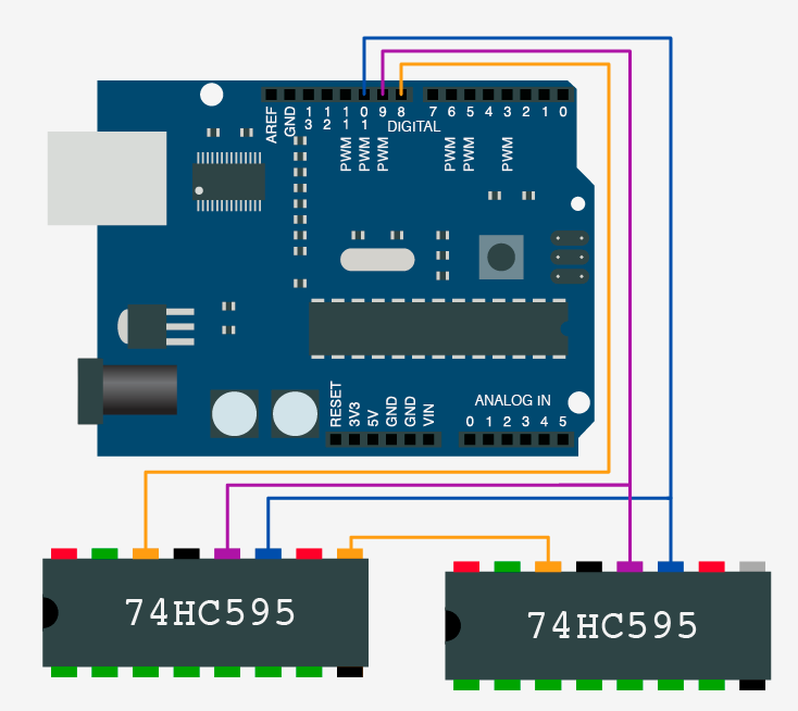
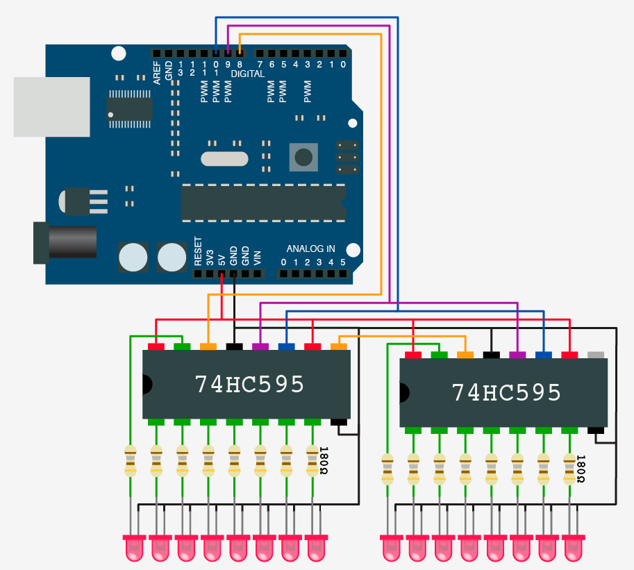
Cascading Shift Register – AKA chaining them together
Like I said above, you could connect 20 of these together if you needed. Shift registers have a pretty clever option built in that allows them to be chained or Cascaded together. You know how the last register just dumps its value when it is shifted over? Well the Qh pin (pin 9) is where the 74HC595 dumps that value. So we just take that and use it as the SER input on a second (or next) shift register, and bam! they are chained together. You will also need to then connect the SERCLK and RCLK pins together, but then you are golden. Check out the schematics to the side and below to see how it is connected.
Code
Arduino code for Individual control over each pin – Support for 40+ shift registers
int SER_Pin = 8;   //pin 14 on the 75HC595
int RCLK_Pin = 9;  //pin 12 on the 75HC595
int SRCLK_Pin = 10; //pin 11 on the 75HC595

//How many of the shift registers - change this
#define number_of_74hc595s 1

//do not touch
#define numOfRegisterPins number_of_74hc595s * 8

boolean registers[numOfRegisterPins];

void setup(){
  pinMode(SER_Pin, OUTPUT);
  pinMode(RCLK_Pin, OUTPUT);
  pinMode(SRCLK_Pin, OUTPUT);


  //reset all register pins
  clearRegisters();
  writeRegisters();
}


//set all register pins to LOW
void clearRegisters(){
  for(int i = numOfRegisterPins - 1; i >=  0; i--){
     registers[i] = LOW;
  }
}


//Set and display registers
//Only call AFTER all values are set how you would like (slow otherwise)
void writeRegisters(){

  digitalWrite(RCLK_Pin, LOW);

  for(int i = numOfRegisterPins - 1; i >=  0; i--){
    digitalWrite(SRCLK_Pin, LOW);

    int val = registers[i];

    digitalWrite(SER_Pin, val);
    digitalWrite(SRCLK_Pin, HIGH);

  }
  digitalWrite(RCLK_Pin, HIGH);

}

//set an individual pin HIGH or LOW
void setRegisterPin(int index, int value){
  registers[index] = value;
}


void loop(){

  setRegisterPin(2, HIGH);
  setRegisterPin(3, HIGH);
  setRegisterPin(4, LOW);
  setRegisterPin(5, HIGH);
  setRegisterPin(7, HIGH);


  writeRegisters();  //MUST BE CALLED TO DISPLAY CHANGES
  //Only call once after the values are set how you need.
}
This code example just turns on the LEDs in a particular pattern and keeps it here. (This code will only support up to 4 shift registers. Because of it taking in a binary number, it is limited to 32 characters.)
Here is code for the AVR
int SER_Pin = 8;   //pin 14 on the 75HC595
int RCLK_Pin = 9;  //pin 12 on the 75HC595
int SRCLK_Pin = 10; //pin 11 on the 75HC595

//How many of the shift registers - change this
#define number_of_74hc595s 1

//do not touch
#define numOfRegisterPins number_of_74hc595s * 8

boolean registers[numOfRegisterPins];

void setup(){
  pinMode(SER_Pin, OUTPUT);
  pinMode(RCLK_Pin, OUTPUT);
  pinMode(SRCLK_Pin, OUTPUT);


  //reset all register pins
  clearRegisters();
  writeRegisters();
}


//set all register pins to LOW
void clearRegisters(){
  for(int i = numOfRegisterPins - 1; i >=  0; i--){
     registers[i] = LOW;
  }
}


//Set and display registers
//Only call AFTER all values are set how you would like (slow otherwise)
void writeRegisters(){

  digitalWrite(RCLK_Pin, LOW);

  for(int i = numOfRegisterPins - 1; i >=  0; i--){
    digitalWrite(SRCLK_Pin, LOW);

    int val = registers[i];

    digitalWrite(SER_Pin, val);
    digitalWrite(SRCLK_Pin, HIGH);

  }
  digitalWrite(RCLK_Pin, HIGH);

}

//set an individual pin HIGH or LOW
void setRegisterPin(int index, int value){
  registers[index] = value;
}


void loop(){

  setRegisterPin(2, HIGH);
  setRegisterPin(3, HIGH);
  setRegisterPin(4, LOW);
  setRegisterPin(5, HIGH);
  setRegisterPin(7, HIGH);


  writeRegisters();  //MUST BE CALLED TO DISPLAY CHANGES
  //Only call once after the values are set how you need.
}
Conclusion
If you need an easy way to extend your output-pins, shift registers are definitely a good choice. They are cheap, fast and if you take the time to play with them, they are pretty simple too.
