Thanks to all the sensors compatible with Arduino board, it is very easy to build a complete weather station. Here is how I proceed.
About components
To achieve this weather station, one should first choose what has to be monitored. I chose temperature, humidity and atmospheric pressure. One could also consider the amount of rain, luminosity, rate of oxygen, etc.. Everything is about finding the appropriate sensor. Be careful about the limited number of pins on your Arduino board. Beyond a certain number of sensors, it may need other components to increase the number of inputs / outputs of the Arduino. Here, we want to keep a simple installation, the following components were used:
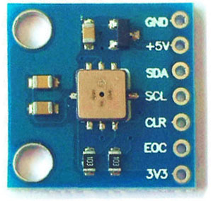
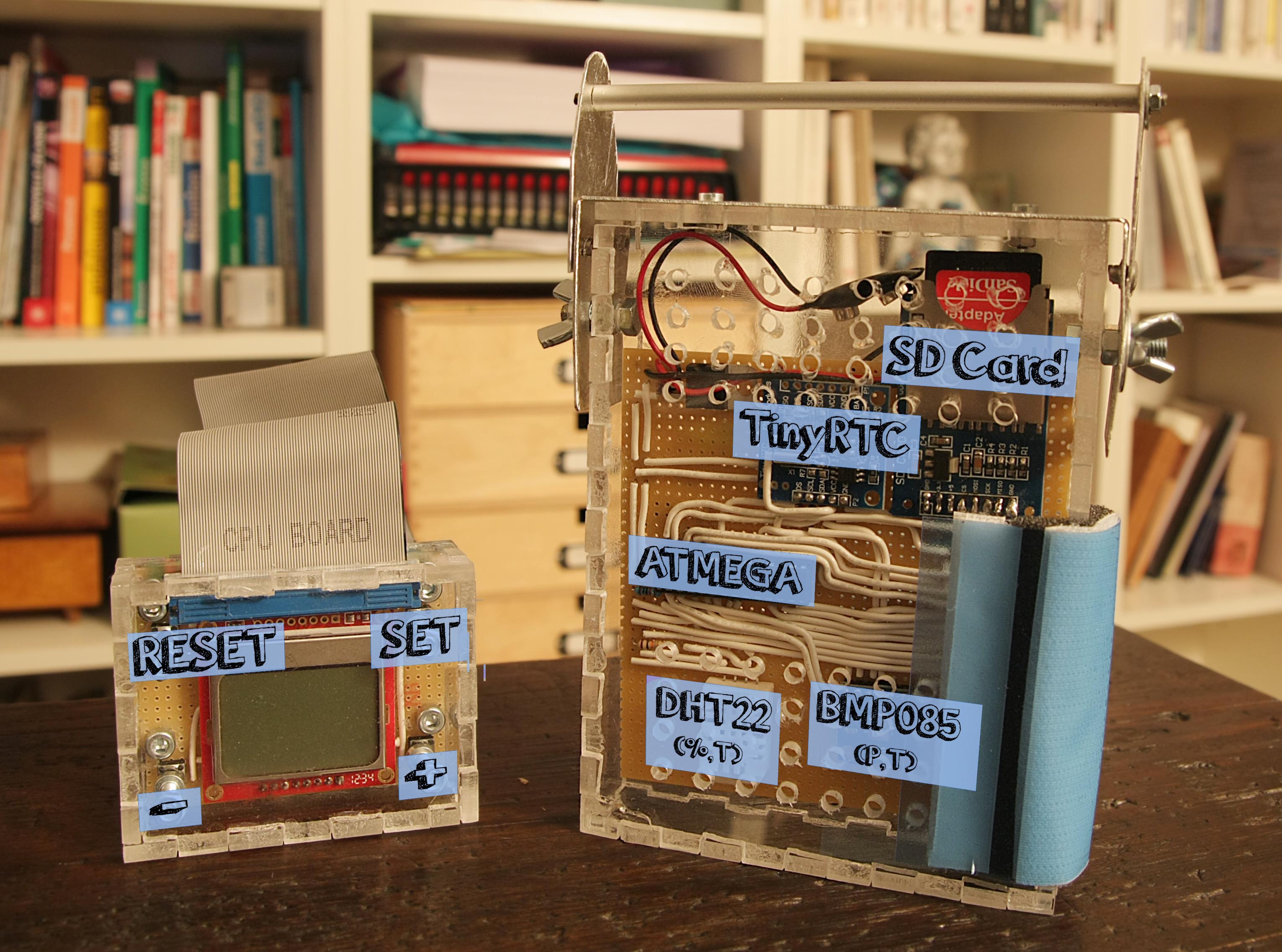
– for pressure, a BMP085
-for humidity, a DHT22
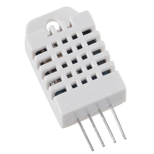
The advantage of these sensors is that they have an embedded temperature sensor used for their own compensation. The one from the BMP085 is the most accurate, but we will record data from DHT22 anyway.
Now that we have the sensors, we need to save data and know at which time they were measured. We then choose:
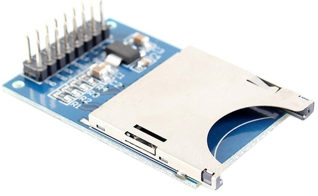
– a SD card breakout to store measurements:
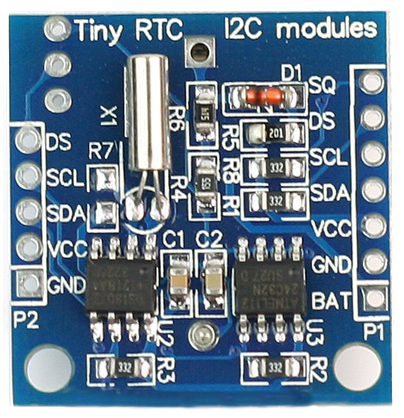
– a component called TinyRTC for Real Time Clock:
At the heart of all this, we add a ATMEGA 328P that will be used with its internal 8MHz oscillator in order to further simplify installation. For power, we want to use a 9V battery, so we add an LM075 which is responsible for the regulation part.
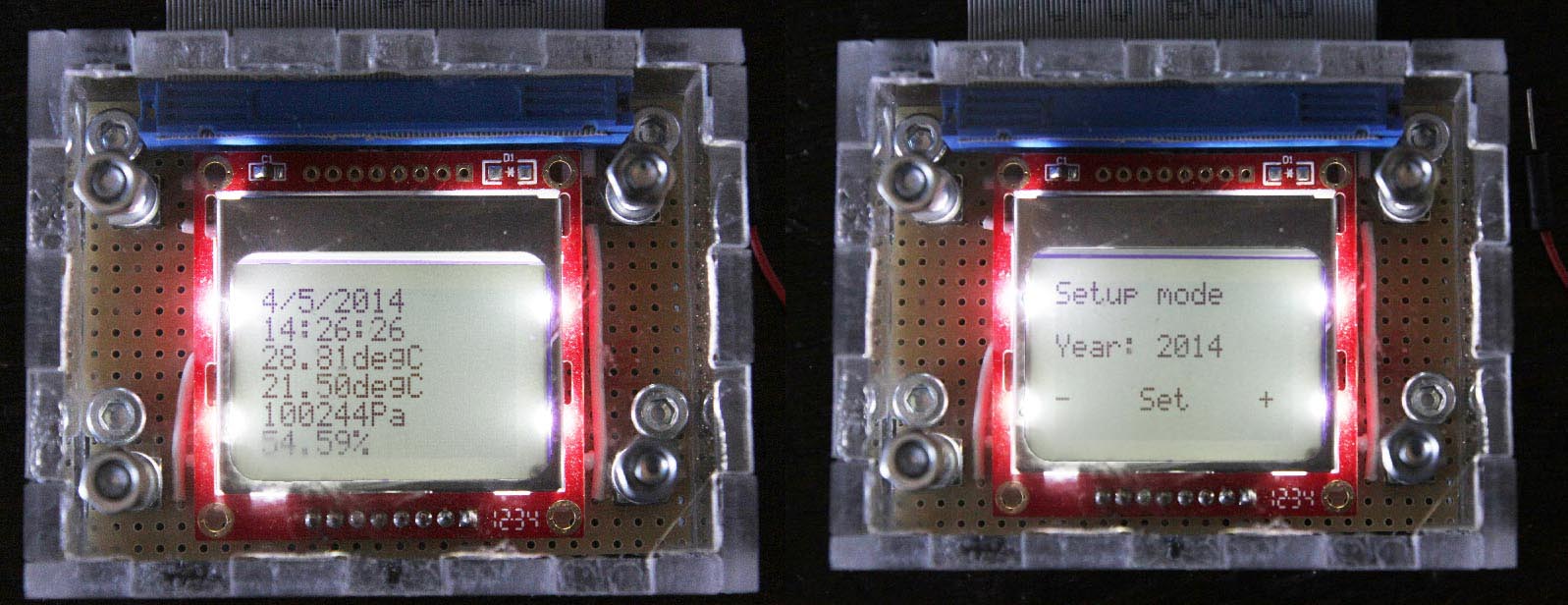
Then, we want to set the date and view sensor values without going through a computer. We then add a Nokia 5110 LCD screen and some push buttons to interact with the ATMEGA.
Some resistors to ensure 5/3.3 volts conversions and here we are, it only remains to make the wiring.
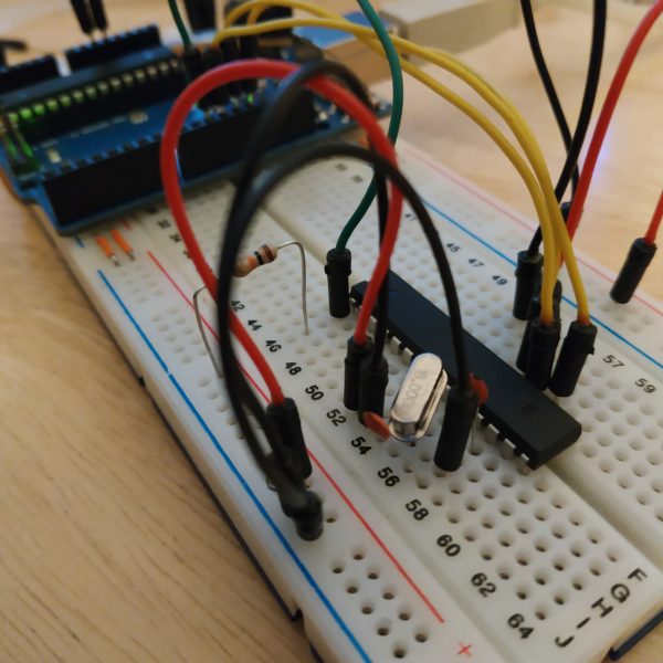
The wiring
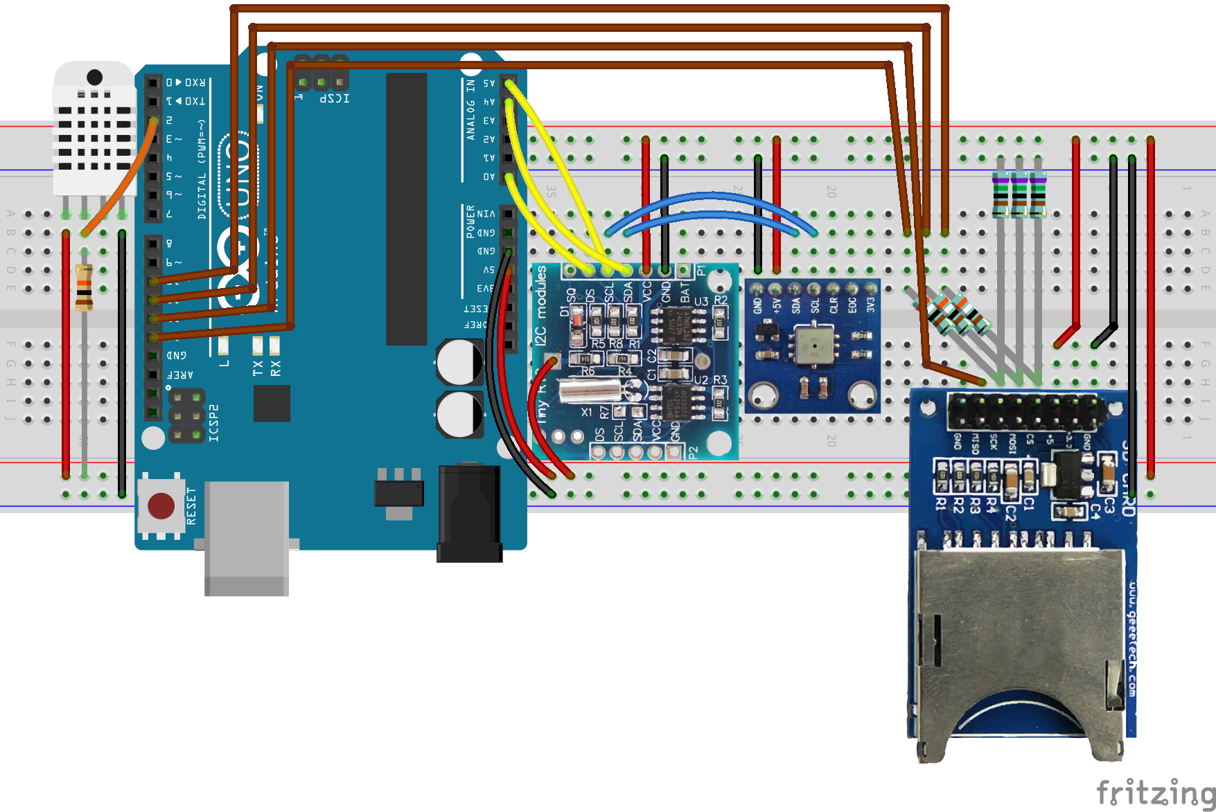
Before welding everything definitely, we work with an Arduino Uno on a prototyping board. For wiring, it is noted that the RTC and the BMP085 communicates both with the I2C protocol, which requires a single loop of wire through the SDA and SCL ports of these two units.
For the SD card, the protocol is a bit more expensive in cable and pins, since in addition to the power supply, it takes 4 pins (MISO, MOSI, CS, SCK).
The DHT22 is the most economical using a single pin for measurement.
We slightly changes the TinyRTC by unsoldering the diode and connecting the power supply directly on battery pins. Indeed, this component is supposed to work with a rechargeable button cell battery, quite difficult to obtain, and in any case, in this arrangement, the power will always be available at least to power the Arduino.
The other available Arduino pins are used to send a display on the LCD screen and retrieve information from 4 pushbuttons.
Here is the wiring with an Arduino Uno without the LCD and pushbuttons. This assembly can already perform measurements and store them on an SD card:
Source and libraries
About the programming part, the most difficult is to find correct libraries that allows to communicate with all units. Here is the list:
– Tiny RTC: Adafruit library available here
– SD Breakout: library for SD available within Arduino IDE and proposed by Sparkfun
– DHT22: Adafruit library available here
– BMP085:Adafruit library available here
We realize that high number of components also means large numbers of libraries. This can become difficult as in the number of pins available than available memory to load program and libraries. This is a parameter to take into account as soon as possible in the design.
Then it only remains to initialize the sensors by assigning the right pins, loop through the measurement and writing to the SD card. As soon as the measurement is done, ATMEGA is idle for a minute. Since we do not wake the ATMEGA via an external interrupt, we can allow only 8 seconds sleeps.We do them until a minute. The loop starts again for the next measurement. Here is the complete code that is loaded directly on the ATMEGA (scroll down to see the full code):
|
1 2 3 4 5 6 7 8 9 10 11 12 13 14 15 16 17 18 19 20 21 22 23 24 25 26 27 28 29 30 31 32 33 34 35 36 37 38 39 40 41 42 43 44 45 46 47 48 49 50 51 52 53 54 55 56 57 58 59 60 61 62 63 64 65 66 67 68 69 70 71 72 73 74 75 76 77 78 79 80 81 82 83 84 85 86 87 88 89 90 91 92 93 94 95 96 97 98 99 100 101 102 103 104 105 106 107 108 109 110 111 112 113 114 115 116 117 118 119 120 121 122 123 124 125 126 127 128 129 130 131 132 133 134 135 136 137 138 139 140 141 142 143 144 145 146 147 148 149 150 151 152 153 154 155 156 157 158 159 160 161 162 163 164 165 166 167 168 169 170 171 172 173 174 175 176 177 178 179 180 181 182 183 184 185 186 187 188 189 190 191 192 193 194 195 196 197 198 199 200 201 202 203 204 205 206 207 208 209 210 211 212 213 214 215 216 217 218 219 220 221 222 223 224 225 226 227 228 229 230 231 232 233 234 235 236 237 238 239 240 241 242 243 244 245 246 247 |
/* SD Card connection: MOSI - pin 11 ; MISO - pin 12 ; CLK - pin 13 ; CS - pin 10 */ // Libraries #include <SD.h> // Library for SD card connection #include <Wire.h> // Library to communicate with I2C modules #include "RTClib.h" // Library to use RTC module #include <Adafruit_BMP085.h> // Library to use BMP085 #include "DHT.h" // library to use DHT sensor #include <PCD8544.h> // library for LCD Screen // Low power #include <avr/sleep.h> #include <avr/wdt.h> // watchdog interrupt ISR(WDT_vect) { wdt_disable(); // disable watchdog } void myWatchdogEnable(const byte interval) { MCUSR = 0; // reset various flags WDTCSR |= 0b00011000; // see docs, set WDCE, WDE WDTCSR = 0b01000000 | interval; // set WDIE, and appropriate delay wdt_reset(); set_sleep_mode (SLEEP_MODE_PWR_DOWN); sleep_mode(); // now goes to Sleep and waits for the interrupt } // Variable declaration #define DHTPIN 2 // Digital pin of DHT sensor #define DHTTYPE DHT22 // DHT 22 (AM2302) DHT myDHT(DHTPIN, DHTTYPE,3); // Instanciate DHT module RTC_DS1307 myRTC; // Instanciate RTC module File myOutputFile; // Instanciate output file char myData[100]; // Contain current data Adafruit_BMP085 myBMP; // Instanciate BMP module static PCD8544 lcd; // instanciate LCD screen uint16_t year; uint8_t month; uint8_t day; uint8_t hour; uint8_t minute; uint8_t second; float temp_BMP; int temp_BMP_int; // Integer part of temperature int temp_BMP_dec; // Decimal part of temperature int32_t pressure_BMP; float temp_DHT; int temp_DHT_int; int temp_DHT_dec; float humidity_DHT; int humidity_DHT_int; int humidity_DHT_dec; int scroll_pin = A3; int increment_pin = A2; int decrement_pin = A1; void setup() { // Start SD card connection : wait for port to open pinMode(10, OUTPUT); SD.begin(10); analogReference(INTERNAL); // Start I2C connections Wire.begin(); // Start RTC module myRTC.begin(); if (! myRTC.isrunning()) { // Following line sets the RTC to the date & time this sketch was compiled myRTC.adjust(DateTime(__DATE__, __TIME__)); } // Start BMP module if (!myBMP.begin()) { //Could not find a valid BMP085 sensor, check wiring } // Start DHT module myDHT.begin(); // Start LCD module lcd.begin(84, 48); // Initiate pin mode pinMode(scroll_pin, INPUT); pinMode(increment_pin, INPUT); pinMode(decrement_pin, INPUT); } void loop() { // Retrieve RTC date DateTime myDateTime = myRTC.now(); year = myDateTime.year(); month = myDateTime.month(); day = myDateTime.day(); hour = myDateTime.hour(); minute = myDateTime.minute(); second = myDateTime.second(); // Retrieve BMP085 data temp_BMP = myBMP.readTemperature(); temp_BMP_int = int(temp_BMP); temp_BMP_dec = int((temp_BMP - temp_BMP_int)*100.); pressure_BMP = myBMP.readPressure(); // Retrieve DHT22 data temp_DHT = myDHT.readTemperature(); temp_DHT_int = int(temp_DHT); temp_DHT_dec = int((temp_DHT - temp_DHT_int)*100.); humidity_DHT = myDHT.readHumidity(); humidity_DHT_int = int(humidity_DHT); humidity_DHT_dec = int((humidity_DHT - humidity_DHT_int)*100.); sprintf(myData, "%u/%u/%u %u:%u:%u %i.%i %li %i.%i %i.%i", year, month, day, hour, minute, second, temp_BMP_int, temp_BMP_dec, pressure_BMP, temp_DHT_int, temp_DHT_dec, humidity_DHT_int, humidity_DHT_dec); myOutputFile = SD.open("Data.txt", FILE_WRITE); myOutputFile.println(myData); myOutputFile.close(); // LCD Display // Date sprintf(myData, "%u/%u/%u", day, month, year); lcd.setCursor(0, 0); lcd.print(" "); lcd.setCursor(0, 0); lcd.print(myData); // Time sprintf(myData, "%u:%u:%u", hour, minute, second); lcd.setCursor(0, 1); lcd.print(" "); lcd.setCursor(0, 1); lcd.print(myData); // BMP085 temp sprintf(myData, "%i.%idegC", temp_BMP_int, temp_BMP_dec); lcd.setCursor(0, 2); lcd.print(" "); lcd.setCursor(0, 2); lcd.print(myData); // DHT22 temp sprintf(myData, "%i.%idegC", temp_DHT_int, temp_DHT_dec); lcd.setCursor(0, 3); lcd.print(" "); lcd.setCursor(0, 3); lcd.print(myData); // BMP085 pressure sprintf(myData, "%liPa", pressure_BMP); lcd.setCursor(0, 4); lcd.print(" "); lcd.setCursor(0, 4); lcd.print(myData); // DHT22 humidity sprintf(myData, "%i.%i%%", humidity_DHT_int, humidity_DHT_dec); lcd.setCursor(0, 5); lcd.print(" "); lcd.setCursor(0, 5); lcd.print(myData); // Enter setup mode if (digitalRead(scroll_pin) == HIGH) { waitForButtonRelease(scroll_pin); lcd.clear(); lcd.setCursor(0, 0); lcd.print("Setup mode"); year = setValue(year, "Year", 2000,2100); month = setValue(month, "Month",1,12); day = setValue(day, "Day",1,31); hour = setValue(hour, "Hour",0,23); minute = setValue(minute, "Minute",0,59); second = setValue(second, "Seconds",0,59); // Write down new date myRTC.adjust(DateTime(year, month, day, hour, minute, second)); }else{ // Enter sleep mode for 60 seconds myWatchdogEnable (0b100001); // 8 seconds if (digitalRead(scroll_pin) != HIGH){ myWatchdogEnable (0b100001); // 8 seconds } if (digitalRead(scroll_pin) != HIGH){ myWatchdogEnable (0b100001); // 8 seconds } if (digitalRead(scroll_pin) != HIGH){ myWatchdogEnable (0b100001); // 8 seconds } if (digitalRead(scroll_pin) != HIGH){ myWatchdogEnable (0b100001); // 8 seconds } if (digitalRead(scroll_pin) != HIGH){ myWatchdogEnable (0b100001); // 8 seconds } if (digitalRead(scroll_pin) != HIGH){ myWatchdogEnable (0b100001); // 8 seconds } if (digitalRead(scroll_pin) != HIGH){ myWatchdogEnable (0b100000); // 4 seconds } } delay(100); } uint16_t setValue(uint16_t value, char * label, uint16_t min_value, uint16_t max_value){ // We enter this method on scroll button push, wait for it to be released waitForButtonRelease(scroll_pin); // Scroll button will exit this method while (true){ delay(10); // Display year and helping symbols lcd.setCursor(0, 2); lcd.print(" "); lcd.setCursor(0, 2); sprintf(myData, "%s: %u",label, value); lcd.print(myData); lcd.setCursor(0, 4); lcd.print("- Set +"); // Wait for action if (digitalRead(scroll_pin) == HIGH){ waitForButtonRelease(scroll_pin); return value; } else if (digitalRead(decrement_pin) == HIGH) { waitForButtonRelease(decrement_pin); value--; if (value == min_value-1){ value = max_value; } } else if (digitalRead(increment_pin) == HIGH ){ waitForButtonRelease(increment_pin); value++; if (value == max_value+1){ value = min_value; } } } } void waitForButtonRelease(int btnPin){ while (digitalRead(btnPin) == HIGH){ } } |
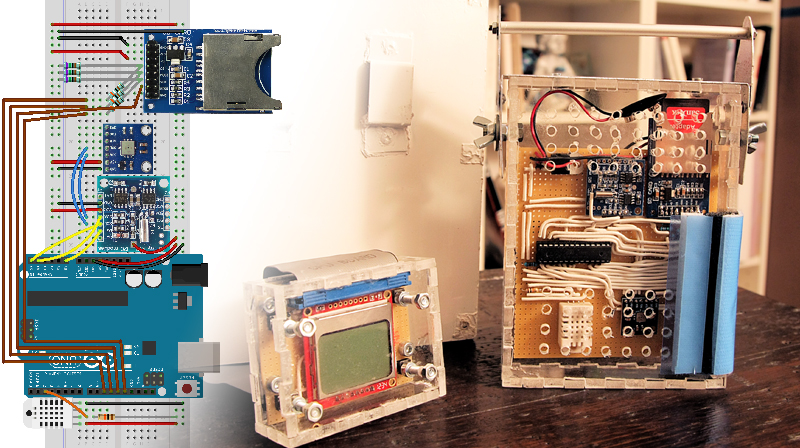
Packaging
It is time to make final assembly for outdoor use.
We opted for two hard plastic cases cut using the jigsaw and assembled with glue. We want to make independent the LCD screen, which would not withstand outdoor conditions, and to use it on several weather stations. The code allows to disconnect it without interrupting the measurement. And the Reset button allows to connect it at any time by restarting the ATMEGA.
For mounting sensors, one side of the box is detachable for easy access to the SD card and battery. Finally an window is made to connect the LCD screen via an IDE ribbon cable. Small holes are made on another side to allow the exchange of air between the outside and the pressure, temperature and humidity sensors. The sensors are positioned at the bottom so that the heat generated by the assembly does not interfere with the measurements. Everything is inserted under a aluminum enclosure, also cut using the jigsaw, assembled by rivets and painted white for not keep heat and distort the measurements. All joins are sealed with silicone to make the station resistant to rain.
Assembly is hung in the alu enclosure by a hook system, and the whole stuff on a tree with a strap.
User manual
- We insert the SD card before connecting the battery.
- After connecting the battery, we connect the screeb using the IDE ribbon cable.
- A push on RESET button allow to restart the unit and to make the screen work.
- A long push (> 8 sec) on SET button allows to enter setup mode.
- We can then set date and hour with + and – buttons.
- After checking all data on screen, we hot-unplugged it and we hang everything within the aluminium enclosure.
- At the end of measurements, we can disconnect the battery and retrieve the SD card
- The content of the SD card can be read onto a computer.
Data are stored onto the SD card under the following format:
|
1 2 3 4 |
2014/1/29 23:4:37 24.43 99933 23.0 45.29 2014/1/29 23:4:47 24.95 99926 23.0 45.29 2014/1/29 23:4:57 25.39 99919 23.0 45.40 2014/3/28 21:0:0 26.6 99938 23.10 45.29 |
We can read the day, hour, temperature and pressure from BMP085, then temperature and humidity from DHT22. We can import them and plot charts automatically using the following Excel sheet : WeatherStationAnalysis.xlsm
Following improvements
The main drawback of this station is power. Many components can be supplied with 3.3V, while we supply 5V, each performing its own conversion, except for the SD card where the conversion is done via resistors. In addition, to get the 5V, we feed the LM075 with 9V. In short, a lot of losses while everythingcan be fed directly with 3.3V. But is it possible to supply a ATMEGA with 3.3V ? This is the question to solve to greatly improve this assembly.
To reduce the impact of this design flaw, we take measurements only once a minute, and during the intermediate time, ATMEGA is in a standby mode, thereby halving the current.
A final improvement would obviously to choose a clock that can wake the ATMEGA every minute, which would allow to turn off all the components for a full minute between two measurements, using the clock to provide an external interrupt.